Suit for all kinds of machine room above lift/elevator
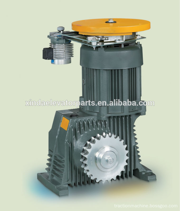
Gearless Traction Elevator for Escalator Machine
Product Characteristics
Drive: VVVF drive
Deadweight: 320kg/430kg
Noise level:<58dB(A)
Torsional vibrations: <0.8~1.2mm/s ;<2.0mm/s
Horizontal and vertical vibrations: <0.8~1.2mm/s
Rated output torque: 886N·m~1463N·m; 1072N·m~2925N·m
Arrangement: right side
Escalator Traction Machine Escalator Geared Traction Machine, Traction Machine for Lift and Escalator, Gearless Traction Elevator for Escalator Machine Ningbo Xinda Elevator Traction Technology Co., Ltd. , https://www.xinda-elevator.com
The main design challenges for LED lighting applications include the following: heat dissipation, high efficiency, low cost, dimming-free flicker, wide-range dimming, reliability, safety, and elimination of color cast. These challenges need to be solved by a combination of appropriate power system topology, drive circuit topology, and mechanical design.
Li Rongquan, marketing director of Hao Rong's explosion-proof technology, pointed out: "For designers, the biggest technical challenge will be high efficiency requirements, optical design, thermal management, and the enhancement of certain application reliability, such as high-brightness LED street lamps. We now offer A range of LED lighting solutions covers applications from 0.1W to 250W." "In the application of LED lighting systems, a complete LED lighting design includes optical design, thermal design, product design, and Electric drive design.Because LED is a low-voltage device, converting low-voltage AC power to low-voltage constant-current drive for LED will face many challenges.†Zhang Rongqian, senior application manager of explosion-proof, pointed out: “Further say, in order to ensure the advantages of LED lighting, LED electric drive must be reliable, high efficiency, safe and low cost. Therefore, for different LED lighting applications, we must first choose the correct drive circuit topology.†Yu Rong explosion-proof can now provide from 30W to 300W All explosion-proof LED lighting solutions in the power range. In order to quickly take off the LED lighting market, National Semiconductor Corporation (NSC) recently aimed at a very large incandescent lamp directly to replace the market, that is, using LED lamps to directly replace incandescent lamps in existing home or other application markets, and launched A direct mains input LED drive chip LM3445 for this market.
However, Wu Zhimin, marketing manager of power management products in NSC Asia Pacific, said: “The incandescent lamp has been available for many years. For many years of unchanging technical standards, our home lighting system has been using many technical standards that have not been changed for many years. The situation may not be changed overnight. For example, based on issues such as heat dissipation and lighting angles, the existing old light sockets or devices are not suitable for installing LED light bulbs. However, in addition to technical issues, the cost-effectiveness of LED lights is also incapable. The biggest reason for popularity is that tungsten bulbs and neon tubes are priced at about US$0.6-0.7/Klm, but the current price of LED lamps is still as high as US$40-50/Klm.†As mentioned above, due to LED lamps Must be able to be installed in the original old socket, so heat dissipation is a big problem that must be overcome. Strictly speaking, this can be solved using mechanical engineering techniques. The responsibility of LED system manufacturers is to develop new technologies and maximize the brightness of the LED (ie, the amount of lumens generated per unit of power). Wu Zhimin confidently said: "We can provide the most efficient LED driver to ensure that the entire lighting system can minimize the amount of heat."
The relatively high cost of LEDs is a major obstacle to the LED lighting market's current difficulty in large-scale take-off. For example, "The majority of LED lighting applications smaller than 25W are marker lights, marker lights, and alternative standard incandescent and halogen lamps. However, compared to existing fluorescent and incandescent lamp technologies, the initial cost of LEDs is still in the mass market. One major obstacle.†Xu Ruibao, an engineer at Cytech's product and design department, also agreed that the main commercial challenge is cost. He said: "At present, all kinds of power LED lighting systems can be achieved on the circuit, technical challenges from the requirements of the terminal applications, such as applied to the car, to consider the optical design and overall thermal design. Commercial deployment of The challenge comes mainly from LED costs."
LED lighting design thermal considerations
LED lighting systems below 25W are generally designed for applications such as reading desk lamps, hallway lamps, living room spotlights, home dining lights, and nightlights. Customers generally hope that these applications are designed to be as compact as possible, so their PCB designs can be placed The space is relatively small, so the temperature inside the package space may be very high when used for a long time. Because designers are less likely to install a cooling fan inside, its thermal design becomes critical and important.
“Most low-power LED lighting applications less than 25W require a certain degree of miniaturization. This often leads to higher power density, although power consumption is not very large. Sufficient thermal management measures must be provided through an improved mechanical structure. In addition, high Electrical efficiency helps to reduce power consumption.†Alexander Sommer pointed out, “If you need to further reduce the thermal resistance, this can be done through electrical isolation because it allows the most efficient heat transfer. These methods also allow for optimized lumen output. ."
Another idea to prevent long-term overheating of LEDs is to use dimming solutions. According to Sang Cheol Her, marketing manager for high-voltage IC products at Fairchild Semiconductor, “Comparing to fluorescent and incandescent lamps, the use of dimming solutions is an important way to reduce the power consumption of LEDs. This approach is implemented using dimming controllers. Less than 25W LED drive solution, due to the small size of the PCB, and the packaging space is limited, the heat problem is unavoidable, so the program is more important."
In fact, in this power range, LED lighting will replace halogen lamps and compact fluorescent lamps (CFLs). In addition, advanced technologies must remove passive components such as electrolytic capacitors that are sensitive to temperature changes in order to get rid of heat dissipation problems. However, most of the current LED driver solutions are based on and based on the power supply topology. Therefore, the temperature range should be considered because the general product is usually based on commercial standards, but the lighting must ensure that it can adapt to harsh environments. Industrial environment.
LED lighting design architecture choice
The choice of LED lighting system architecture depends on whether your design goal is low cost, high efficiency, or minimal PCB area. In general, LED lighting systems less than 25W do not require power correction, so it is possible to adopt a simple topology structure such as PSR or Buck topology. 25W-100W LED lighting applications require power correction, so generally use single-stage PFC, quasi-resonant (QR) PWM or flyback topology. More than 100W LED lighting applications generally use more efficient LLC topology and two-stage PFC.
"Below 25W power LED lighting solutions can use PSR or Buck topology, because this power range is mainly for small designs, emphasizing the simplicity of design. Medium power solutions (25W-100W) suitable for single-stage PFC, quasi-resonant ( QR) PWM, flyback topology." SangCheolHer said, "High-power solutions (greater than 100W) are suitable for LLC, QRPWM, flyback topology design. From an efficiency point of view, LLC and QR performance is better; and PSR The scheme does not require secondary feedback, the design is simple, and the size is smaller than other schemes."
Zhang Zongqian also said: "Less than 25W LED lamps are mainly used in indoor lighting, they mainly use low-cost flyback topology. ON Semiconductor's NCP1015 and NCP1027 monolithic integrated circuit integrates a built-in high-voltage MOSFET and PWM controller. Effectively reduce the area of ​​the PCB and the size of the lamp, providing a maximum 25W power output (230VAC input)."
“For non-isolated, less than 25W LED lighting applications, if the input-to-output conversion ratio is low, then a simple buck converter can be a low-cost, small-footprint choice. In an isolated topology that emphasizes efficiency, use something like The quasi-resonant flyback topology of the explosion-protected Cool SETICE2QS devices is a good choice,†said Alexander Sommer. It is the first supplier to provide digital quasi-resonant flyback control ICs.
Typical LED lighting applications for the 25W-100W power range are street lighting (cell roads) and public spaces like parking lots. Power conversion efficiency, cost-effective implementation of the PFC function and high color quality are now the three most important technical challenges. For example, in commercial lighting and street lighting applications, longer service life and resulting lower maintenance costs are helping to overcome the barriers to entry of higher initial costs. 25W to 100W LED lighting applications have power factor requirements, so an additional power factor correction circuit is needed.
"This circuit can use the traditional two-stage structure, ie, active discontinuous mode power factor correction (PFC) circuit plus DC-DC PWM conversion circuit, such as the NCP1607 power factor correction controller of Nexron explosion-proof, the peripheral circuit of NCP1607 is very Simple and can provide very good performance." Zhang Zongqian said, "For high efficiency, low cost and small size of the LED program, it is worth recommending a single-stage PFC circuit, which can achieve both power factor and isolated low-voltage DC The output, with significant cost advantages, will surely become the mainstream solution for medium-power LED lighting. Nvidia's explosion-proof NCP1652 provides the best control solution for implementing a single-stage PFC circuit."
Shenzhen Shiqiang Telecom adopts Silicon Labs' C8051F3XX series of 8-bit MCUs to implement PFC in a software manner. Huang Sunfeng, assistant market manager of the company, said: “We developed 10W-30W low power LED lighting applications for home electric power (180V-260V) input. The all-digital LED lighting solution can achieve a PFC value as high as 0.95 in a software-controlled manner.Compared with the hardware PFC, this set of software solutions is also more flexible, adaptable and scalable under the premise of guaranteeing the same performance indicators. "The maximum output current of the LED driver MIC3230 used in this solution is 350mA, and it can drive up to 12 1W LEDs, which can well meet the needs of indoor lighting."
Alexander Sommer said: "For 25W-100W power LED lighting applications that require efficiency and performance over a wide input and/or load range (such as dimming), a quasi-resonant flyback with an independent PFC stage is recommended. Topology. Typically up to 90% efficiency can be achieved."
Applications above 100W include major road and highway lighting (where brightness is required up to 20K lumens or more, and 250W of power input) and professional applications such as stage lighting and architectural floodlighting. One of the key drivers for using LEDs in high power applications is low cost of ownership due to reliability and low power consumption. For example, its system efficiency can be compared with metal halides and low pressure sodium lamps. The initial cost comparison may continue to be the entry barrier for the market in the short term.
Zhang Zongqian pointed out: "For LED applications larger than 100W, we will use the traditional active discontinuous mode power factor correction circuit and half-bridge resonant DC-DC conversion circuit. We have introduced a new integrated controller that integrates Source discontinuous mode power factor controller and half-bridge resonant controller with high voltage drive."
The half-bridge resonant controller operates at a fixed switching frequency and a fixed duty cycle, and the circuit does not require an output side feedback control loop. This allows the half-bridge resonant DC-DC converter circuit to operate in the most efficient ZVS and ZCS states. The DC output voltage will follow the output of the power factor correction circuit.
Alexander Sommer emphasized: “For higher power LED lighting applications above 100W, efficiency becomes more important, and it is recommended to use the LLC resonant topology, which can achieve more than 90% efficiency. We recommend that you use the new 8 Lead Foot device ICE1HS01."
Regardless of the output power of the LED lighting system, the choice of LED driver circuit will largely depend on the input voltage range, the cumulative voltage drop of the LED string itself, and the current needed to drive the LED. This has led to a variety of different possible LED driver topologies, such as buck, boost, buck-boost, and SEPIC. Tony Armstrong, director of product marketing for Linear Technology’s Power Products Division, pointed out: “Each topology has its advantages and disadvantages. Among them, the standard buck converter is the simplest and easiest to implement, boost and drop. The pressure-boost converter is the second, and the SEPIC converter is the most difficult to implement, because it uses a complex magnetic design principle, and requires the designer to have superb switch mode power supply design expertise. "In short, the end product The application determines the topological structure of the LED, and then the Buck, Boost, SEPIC, or Buck-Boost structure is reasonably selected based on the LED topology and input power. "Generally speaking, Buck is used more often than 25W. More power tends to choose the Boost structure. In terms of efficiency, both can generally achieve more than 85%, and the LT3755 can achieve up to 97% efficiency. Consider the driving part. When the BOM costs, we should consider the overall system cost.†Xu Ruibao said, “With the intensification of competition, there will always be a lower BOM cost program, but not necessarily the most appropriate. We do not recommend the design of products in accordance with this standard. The area of ​​the PCB is mainly controlled by major components, and low-power LED lamps should be highly integrated, and high-power solutions should use products with high technology integration and simple peripheral circuits. s solution."
Li Houquan also pointed out: "In order to achieve high efficiency requirements, switch mode LED drivers should be considered, and most of these customers prefer to choose step-down LED drivers because the total efficiency is higher. If the switch is considered from the lowest BOM cost, the switch LED converters are not the cheapest. Such customers may try to use linear constant current LED drivers. This can provide the lowest BOM cost, but the efficiency may not be as high as a switch mode LED driver, such as from the smallest PCB area From a point of view, switching mode converters will usually be chosen because they generate less heat and even the associated components will be smaller."
Analog, PWM, and TRIAC dimming solutions LED dimming solutions and specifications have been constantly changing and have not been fixed until now, so there are currently three dimming solutions for PWM, analog, and thyristor (TRAIC) on the market. PWM and analog methods are relatively simple, but they require the construction of a dimming infrastructure and a new dimming controller.
The disadvantage of the analog dimming scheme is that the adjustment range of the LED current is limited between a certain maximum value and about 10% of the maximum value (10:1 dimming range). Because the chromatogram of the LED is related to the current, this method is not suitable for certain applications.
The PWM dimming scheme switches between zero current and maximum LED current at a rate that is fast enough to mask visual flicker (usually above 100 MHz). This duty cycle changes the effective average current so that a dimming range of up to 3000:1 can be achieved (limited only by the minimum duty cycle). Since the LED current is either at its maximum value or turned off, this method also has the advantage of avoiding LED color shifts when the current changes, which is common with analog dimming.
Sang Cheol Her is optimistic about the market prospects of the TRIAC dimming solution. He said: "TRIAC (2-wire dimming) will become a very popular solution because it can completely use the traditional system without any In addition, it can also be extended to 3-wire dimming to avoid defects associated with low power factor values."
TRIAC dimming is a very hot topic in the industry today. Initially, TRIAC dimmers were designed for incandescent lamps, but most users want the same TRIAC dimmer to also dim the alternative LED lights. Liang Houquan said: "Diodes Zetex can currently provide customers with all dimming solutions (including PWM, analog and TRIAC). For example, ZXLD1362 LED driver uses an ADJ pin to achieve analog and PWM dimming, which brings customers Great design flexibility."
However, Zhang Zongqian believed that the application scheme of TRIAC dimmers in the market should only be transitional. In the long run, PWM dimming should be used. He said: "The main three decisive factors are: 1) There will be no flickering from PWM dimming from zero to the most light. 2) The performance will be better because the dimming output power adopts power factor correction circuit. This is in line with the global mandatory requirements for the use of power factor for lights, although generally this requirement starts from 25W, but the United States requires that the light from the zero-watt required mandatory power factor correction circuit, such as the use of TRAIC dimming will sacrifice power The factors and the complexity of the circuit increase, so the choice of using PWM dimming can provide the best performance, and it is also a future trend.3) The cost will be better.Adjusting the duty cycle with PWM does not require too much extra control circuit. cost."
Alexander Sommer is also optimistic about the prospects of PWM dimming solutions. He said: “Compared with analog dimming methods, LED's PWM dimming method has the following advantages: 1) Higher efficiency; 2) No matter how dimmed, the LED is always allowed Work in an optimized and constant current group; 3) The hue of the LED color remains the same throughout the entire dimming range (color tones change as the lumen output varies with the LED operating current.)
Xu Ruibao also frankly said: “Individuals feel that the choice of modulation method should not be determined by the power of the LED. It should be determined by the application requirements of the end product. For example, the display backlight or LED decorative light may use PWM dimming method. The color consistency is good and the brightness level is high, but for general household lighting or commercial lighting, analog dimming or TRIAC can also be selected, but color shift will occur, and the level of dimming will be very low."
Li Houquan also stated: “To achieve flicker-free performance in continuous dimming, most customers prefer to choose PWM dimming because it provides a larger dimming range and better linearity. It depends on the dimming frequency you are using. The flicker can be minimized. Analog dimming is easier to implement because it requires only one DC voltage to dim the LED without flicker. However, the dimming range is usually narrower."
For high-power lighting applications made up of multiple LEDs, ensuring that each LED has a uniform brightness without any flicker is also a major design obstacle, but the PWM method can easily solve the problem of flickering when dimming. "If the duty cycle of the PWM modulator can be kept constant, there should be no problem of uneven brightness," Wu Zhimin said. "The National Semiconductor LED driver not only ensures a uniform output current, but also ensures that The picture has extremely high contrast between light and dark. From these aspects, our LED drivers are superior to their peers in the market."
Tony Armstrong pointed out that, in short, the dimming method used by end users will largely be determined by the end use of the LED itself. For example, in a car infotainment system where LEDs are used to provide backlighting to displays, the range of brightness variations in ambient lighting is very wide, ranging from bright when there is plenty of sunlight to the darkness of moonless nights. Since the human eye is extremely sensitive to slight changes in ambient lighting conditions, a wide 3000:1 wide dimming range is required. This will require the LED driver circuit to use the PWM dimming method.
However, he added: "In LED street lights, since this type of lamp is often either on or off, only a limited dimming range is needed. In this case, only one must be used. A simple analog dimming method can meet the requirements."
As mentioned earlier, LED lighting applications less than 25W are primarily replacing standard incandescent and halogen lamps. In this power range, the most likely application is to replace incandescent or energy-saving lamps controlled by TRIAC (triac)-based step-down wall-in dimmers. There are cutting edge and trailing edge dimmers on the market today, which presents challenges for overall compatibility because TRIAC dimming is very poor from an EMI perspective.
"For non-dimming applications that require cost-effectiveness, using a single-stage PFC flyback topology such as the DMP CPF 3083G is an appropriate choice." Alexander Sommer believes that "25W and above power range LED lighting applications for more The professional market.The choice of dimming control method will depend on whether it is an alternative or a new installation.Digital lighting control (such as DALI or wireless solutions) allows more precise control of the dimming level, and more features, such as Daylight dimming and duty cycle sensing. Alternative installations may require compatibility with older analog 1-10V dimming controllers."
Escalator Traction Machine
Specifications
energy-saving, less maintenance, low noise
Size power LED lighting application options
Whether it is high-power or low-power LED lighting applications, it is generally composed of power supply, LED driver, LED, lens and substrate. The key component is the LED driver, whether it is high-power or low-power LED lighting. Applications generally consist of power, LED drivers, LEDs, lenses, and substrates. The key component is the LED driver. It must provide a constant current output to ensure that the light emitted by the LED does not flicker and The phenomenon of LED color shift occurs. It generally accepts 24V-48V DC voltage input, but there are also some advanced LED drivers that can directly accept 220V AC input. Most customers require high-performance LED drivers to meet upcoming LED lighting specifications such as "PF value of 0.9" and "+85 efficiency."