Tower Crane fixing angle is used for the fixation of one sets of tower crane. Usually the fixing angle is installed into the ground together with the pouring concrete. Based on whether the fixing angle could be reused or not, it has been divided into two types, one is Tower Crane Fixing Angle, the other is Tower Crane Reusable Fixing Angle. Fixed Leg Fixing Angle,Reusable Fixing Angle,Tower Crane Fixing Angle,Tower Crane Reusable Fixing Angle,Foundation Anchor Fixing Angle SHEN YANG BAOQUAN BUSINESS CO., LTD , https://www.sytopkittowercrane.com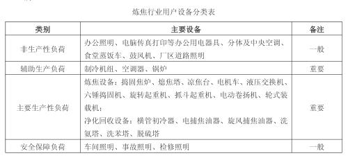
IV. IV. Industry users participate in the peak-to-peak power-limiting risks and precautions. Industry users participate in the peak-to-peak power-limiting risks and precautions 1. The furnace body, fire-fighting parts in the production areas of the production enterprises in the industry encounter sudden power outages, which may easily lead to gas explosion. Leakage, resulting in environmental pollution, can lead to poisoning accidents or large economic losses. It is recommended to use centralized production and centralized maintenance to complete the production tasks in this month ahead of time, and the remaining days at the end of the month to avoid peaks or annual maintenance. 2. From a safety point of view, such as purification product recycling workshop (gas purification), if a sudden power outage occurs, it will lead to a major accident. The reason: the gas coming out of the coke oven reaches 82 °C. If the power is cut off, the fan is shut down, the gas overflows, and Personal injuries and deaths such as explosions and poisoning. For coke ovens, if the power is cut off, the coke oven will be scrapped, and the same gas may explode. Therefore, users in this industry should formulate effective contingency plans as soon as possible. When participating in peaks, they should actively cooperate with the implementation of peaks, communicate with power supply companies in a timely manner, and adopt maintenance or rotation, etc., to avoid forced power or remote control equipment to limit power consumption. A vicious accident occurs, taking the initiative to take social responsibility while minimizing losses.
5, 5, the function and application of intelligent power monitoring Intelligent power monitoring functions and applications 5.15.1 Project Overview Project Overview Uttam Steel in India is rich in coal in Wardha (Wardha area) in Maharashtra With iron ore resources and convenient transportation, there are roads and railways to build a pig iron plant with an annual output of 500,000 tons. The supporting projects include a sintering plant and a 500,000 tons coking plant. The entire project is expected to invest 11 billion rupees (228 million). US$) The construction of the 500,000-ton coking plant includes production facilities such as coal preparation workshops, coking workshops, gas purification workshops, and supporting public auxiliary facilities. As an energy supply area for other plants, power distribution safety is particularly important, and requirements are also more High, in the power control must be required to be safe, reliable and fast, relying on manual on-site control can not meet the actual requirements of the project. Encore Electric Co., Ltd. was commissioned by Shanghai Delixi Co., Ltd. to construct and debug the intelligent power system on the site of the coking plant in India. It mainly completed the centralized monitoring of the 6.6KV power distribution system and 0.4KV power distribution system in the coking plant to ensure coking. The power supply system of the plant is operating normally. 
The 33 station control management station management layer is configured as EVOC IPC-810B Core2 2.66G /1G/160G + mouse and keyboard + speaker. Shenzhen EVOC Industrial Computer (IPC810B) completes the functions of computer monitoring system management, database management, online and offline calculation, operation monitoring control, generation of graph curves, data reporting and other system monitoring. Computer main configuration: CPU: PIV 3.0 memory: 1G hard disk: monitoring workstation 160G display: Samsung 19-inch widescreen LCD display interface: 1000M Ethernet, RS232 interface, LPT port, BNC video output interface, 4 PCI, 2 USB ports, Sound card, 14-slot industrial grade backplane, etc. DVD/VCD optical drive recorder 4U standard rack-mounted chassis walker speaker set (for audible alarm) This computer is industrial computer, large air volume fan design, open door pullable removable filter, Reliable heat dissipation, easy maintenance, special anti-seismic measures to ensure the normal operation of the machine in harsh industrial environments; UPS power supply for C1KS/1KVA standby 30-minute tower
(b) (b) System system 6.6KV6.6KV main interface main interface 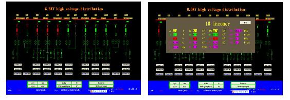
((2 2) Low-voltage contact or outlet circuit selection) Low-voltage contact or outlet circuit selection ACR220ELACR220EL Power meter power meter The main functions of this table are: LCD display, all-electric parameter measurement (U, I, P, Q, PF, F); Four-quadrant energy metering, multi-rate energy statistics, maximum demand statistics; 4DI+2DO; RS485 communication interface, Modbus protocol. Dimensions: 96 × 96mm, opening size: 88 × 88mm. Suitable for low-voltage commissure cabinets, outlet cabinets. ((3 3) Low-voltage outlet cabinet selection) Low-voltage outlet cabinet selection ARDARD series series This meter measures three-phase current, fixed value inquiry, fixed value setting, overload, phase failure (unbalance), stall, underload, external fault, Protection functions such as blocking and undervoltage, 8DI+4DO, power management, leakage protection, SOE recording, multiple start modes, RS485 communication interface, MODbus protocol/Profibus-DP protocol are optional.
((4 4) energy-saving product optional rail table or) energy-saving product optional rail table or APFAPF active filter device active filter device lighting box DDSF1352 main function of the meter: current specification 1.5 (6) A, 5 (20) A, 10(40)A, 20(80)A Optional, multi-rate energy statistics, energy pulse output, RS485 communication interface, Modbus protocol or DL/T 645 protocol optional. Dimensions: 76 × 89 × 74mm, 4 modules. Current and voltage measurement for lighting boxes; single-phase energy metering. ARDDTSF1352 main function of rail type electric meter: current specification 1.5 (6) A, 5 (20) A, 10 (40) A, 20 (80) A optional, multi-rate energy statistics, energy pulse output, RS485 communication interface, Modbus The protocol or DL/T 645 protocol is optional. Dimensions: 126 × 89 × 74mm, 7 modulus. Three-phase energy metering for lighting boxes.
Main functions of DTSD1352 rail type electric meter: LCD display, full electric parameter measurement (U, I, P, Q, PF, F, S); four quadrant energy metering, multi-rate energy statistics, maximum demand statistics; current specification 1.5 ( 6) A, 5 (20) A, 10 (40) A, 20 (80) A optional, RS485 communication interface, Modbus protocol or DL/T 645 protocol optional. Dimensions: 126 × 89 × 74mm, 7 modulus. Suitable for power cabinets. The ANAPF series of active power filter devices are connected to the grid in parallel. By detecting the harmonic and reactive components of the load in real time, PWM converter technology is used to generate a corresponding harmonic component and reactive component from the converter. The inverse component is injected into the power system in real time to achieve harmonic control and reactive power compensation.
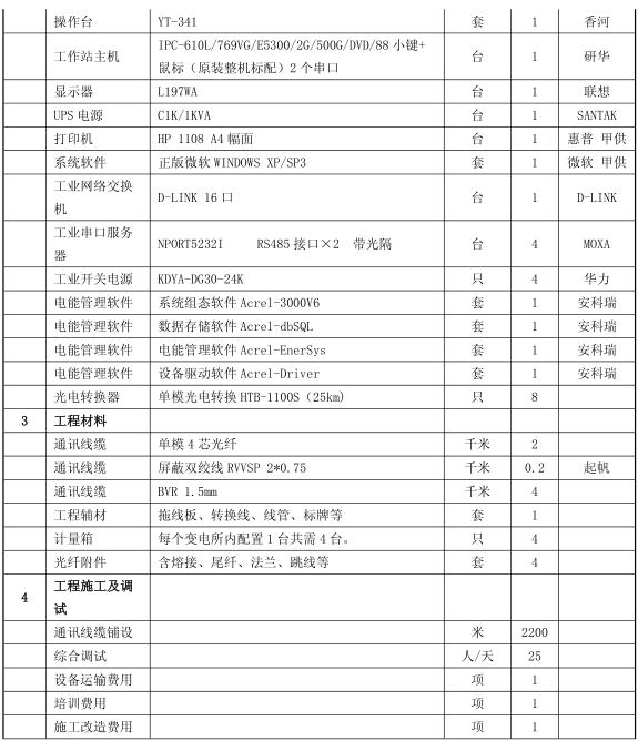
Seven, equipment list VII, equipment list 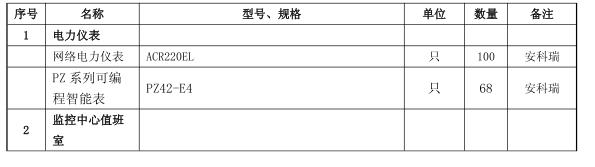
Application of power demand side management and intelligent power monitoring technology in the coking industry's peak-to-peak power-limited power demand side management and intelligent power monitoring technology in the application of peak-to-peak pow
I. Analysis of electricity consumption characteristics of industrial users 1. Analysis of electricity consumption characteristics of industrial users The coking industry refers to the production and operation of coke, as well as the recovery and processing of gas, coal tar and crude benzene produced by coke production. In the industry, coking products are widely used in the chemical industry, pharmaceutical industry, refractory industry and defense industry. In recent years, the rapid development of the steel industry has driven the rapid growth of China's coking industry. The characteristics of the electricity load in the coking industry: 1) Most of the equipment needs continuous operation, such as coke oven, circulating water system, gas recovery unit, etc.; 2) Partially intermittent production, such as machining equipment, coal handling system. Coking production electricity is a primary and secondary power load, and the power supply should be a dual power supply. The two power supplies should be powered in active/standby mode. In order to meet the production power, coking production and distribution systems generally set up two workshop substations - coal char substation, recycling substation. 11 Field equipment layer The field equipment layer is shown in Figure 1 as the 6.6KV system topology diagram. The 6.6KV high voltage power distribution cabinet mainly consists of 2 incoming line cabinets (main incoming line cabinet, spare incoming line cabinet), 2 PT cabinets, 4 A transformer outlet line cabinet, 2 motor outlet cabinets, and 1 mother unit are prepared for the cabinet. In this system, Ankerui Electric Co., Ltd. in order to meet the requirements of users in the high-voltage loop circuit and in order to save costs for users, the field equipment layer configuration: on the 2-way inlet cabinet, choose 2 ACRM4 of our company. -F comprehensive protection (LCD display, line protection measurement and control device, integrated measurement and control device, fault recording, SOE event recording, remote communication, etc.); 2 sets of ACRM4-M comprehensive protection for our 2 motor outlet cabinets (LCD display, motor protection, integrated measurement and control device, fault recording, SOE event recording, remote communication, etc.); 4 sets of ACRM4-T comprehensive protection (LCD display, distribution) for our 4 transformer outlet cabinets Electrical protection measurement and control device, integrated measurement and control device, fault recording, SOE event recording, remote communication, etc.) 2 sets of ACRM4-U of our company on 2 PT cabinets (LCD display, two-stage PT power supply switching, PT Full comprehensive protection of the cabinet, integration of measurement and control devices, fault recording, SOE event recording, remote communication, etc.; on a single parent-child self-contained cabinet The system provides a simple, easy to use, and good user interface. Using the English interface, the CAD graphic shows the electrical main wiring diagram of the power distribution system, showing the status of the power distribution system equipment and the corresponding real-time operating parameters, screen timing wheel patrol switching; real-time dynamic refresh of the screen; analog quantity display; switch quantity display; continuous recording Display and so on. On the 6.6KV system one-time diagram, through the change of the screen color (red indicates the closing state, green indicates the opening state, gray indicates the hand-car separation state), the on-site circuit breaker running state, the handcart position and the grounding knife gate state can be seen. , spring energy storage state, etc. Log in to the ordinary privileged user. Through the operation of the main interface, you can view the electrical parameters (current, voltage, active power, reactive power, power factor, power, and operation) of each 6.6KV circuit. Login to the highest privilege user can realize the on-site circuit breaker. Realize the opening and closing control, view the fixed value of the comprehensive insurance, and modify the fixed value online. (c) 0.4KV (c) 0.4KV system system AA and 0.4KV0.4KV system system BB operation interface operation interface When an operation failure occurs in the distribution system, an audible and visual alarm will be issued in time to prompt the user to respond to the fault circuit in time, and the time and loop name of the event will be automatically recorded for the user to inquire and recall the cause of the failure. (e) (e) Trend curve analysis trend curve analysis ((1 1) High-voltage circuit or low-voltage incoming circuit selection) High-voltage circuit or low-voltage incoming circuit selection ACR330ELHACR330ELH Instrumentation This table is a power quality analysis instrument. The main functions are: LCD display, full-electric parameter measurement (U, I, P , Q, PF, F, S); four-quadrant energy metering, multi-rate energy statistics; THDu, THDi, 2-31 harmonic components; voltage peak factor, telephone waveform factor, current K coefficient, voltage and current Unbalance calculation; grid voltage current positive, negative, zero sequence component (including negative sequence current) measurement; 4DI+3DO (DO3 overvoltage, undervoltage, overcurrent, unbalance alarm); RS485 communication interface, Modbus protocol or DL/T645 Statute. Dimensions: 120 × 120mm, opening size: 108 × 108mm. Suitable for high-voltage important circuit or low-voltage incoming line cabinet.
Second, second, the industry users participate in the peak-to-peak power-capacity analysis industry users participate in the peak-to-peak capacity analysis 1. The industry's electricity load is large and continuous load is not affected by time, season, climate. 2. Emergency peak power limit can quickly disable office equipment such as office, lighting, computer fax machines, etc. At night, you can stop the lighting equipment in the factory area and stop some auxiliary production equipment, such as: refrigeration Units, air conditioners, boilers, but without prejudice to safety. Weak emergency peak capacity, purification and recovery equipment: such as horizontal tube primary cooler, electric tar catcher, cyclone tar catcher, ammonia washing tower, benzene washing tower, desulfurization tower and other important (high risk) power load, not suitable for rapid participation Avoid the peak. 3. The staged peaks of users in this industry can be carried out by arranging centralized maintenance and production reduction. For example, centralized maintenance is required, and only maintenance equipment such as workshop lighting, accident lighting, and maintenance lighting is reserved. Generally, maintenance of about 1000 kW is reserved. The load can be used; if the production mode is discontinued, the coking equipment and the auxiliary system can be gradually stopped to reduce the production load and achieve the peak effect. Third, third, industry users participate in the peak-to-peak power-limiting technology program industry users participate in the peak-to-peak power-limited technology program (1) Gap level IV-level participation program 1. Staged peak: On the premise of ensuring safety, at 8:00~ 22:00 Stop the coke oven for smoldering treatment, reduce the output, and achieve the peak effect. 2. Emergency peak 1) After receiving the peak error command, it is necessary to quickly input the limit load, and then gradually release the load according to the instruction to resume normal production. 2) Prioritize the peaks of the air conditioning system, office and lighting system, and then gradually release the load according to the instructions. (ii) Gap Level III Participation Programme
1. Staged peak: Under the premise of ensuring safety, on the basis of the implementation of the IV-level plan, some machining equipment will be stopped at 8:00~22:00 to participate in the peak, and the coke oven will be treated as a smoldering furnace to further reduce Yield to meet peak demand. 2. Emergency peak 1) After receiving the peak error command, it is necessary to quickly input the limit load, and then gradually release the load according to the instruction to resume normal production. 2) On the basis of the implementation of the IV-level plan, additional machining equipment is added to participate in the peak, reduce part of the production load, so as to meet the peak demand, and then gradually release the load according to the instructions to resume normal production. (3) Gap Level II Participation Plan 1. Staged peaks: 1) On the premise of ensuring safety, on the basis of the implementation of the Level III plan, stop all machining equipment, on 8:00~22:00 Coal blending system equipment further reduces production to meet peak demand. 2) For the purification and recovery equipment with slow response time, it is necessary to participate in the peak preparation in advance to ensure that all load-limited loads can participate in the peak at full time. 2. Emergency peak 1) After receiving the peak error command, it is necessary to quickly input the limit load, and then gradually release the load according to the instruction to resume normal production.
2) On the basis of the implementation of the III-level plan, quickly stop all machining equipment, coal handling system equipment to meet the peak requirements, and then gradually release the load according to the instructions.
(4) Gap level I participation program 1. Staged peak: Considering the large power gap, the company can arrange maintenance throughout the plant, and only retain the power load required to repair the equipment.
2. Emergency peak 1) After receiving the peak error command, it is necessary to quickly input the limit load, and then gradually release the load according to the instruction to resume normal production.
2) Considering the safety of production in the industry and the difficulty of restoring production, no additional production equipment will be added to the implementation of the Level II program. Then gradually release the load according to the instructions.
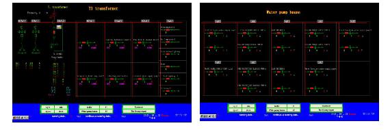
As shown in Figure 2, the 0.4KV system A topology diagram mainly monitors the three-phase current, voltage, and electrical parameters in the pump house.
Ankerui Electric Co., Ltd. is equipped with PZ42-E4 power meter according to customer's demand. The power meter can measure three-phase current, three-phase voltage, active power, reactive power, power factor, power, etc. , embedded installation method; fully meet the requirements of customers, and easy to install, cost-effective.
As shown in Figure 3, the 0.4KV system B topology diagram mainly monitors the motor power parameters of the coal preparation workshop and the coking workshop.
The user mainly looks at the three-phase electric current, voltage, electric energy and other electrical parameters of the motor, as well as checking the running state of the motor and modifying the fixed value.
According to the customer's needs, Ankerui Electric Co., Ltd. also supplies the power meter with PZ42-E4 power meter to collect on-site electrical parameters (with motor protection device on the motor protection circuit)
22 Communication Management Communication Management Communication Management: Adopt Taiwan MOXA CP134U-I communication expansion card, with more than 800 Kbps data throughput, the world's first performance, 4 ports with ADDC? RS-422/485 interface speed up to 921.6 Kbps, 4-wire RS-485 transmission distance up to 1.2 km, built-in 15 KV ESD surge protection or optional 2 KV opto-isolation protection, 128 byte FIFO driver and built-in support Software and hardware flow control, universal PCI compatible with 3.3/5V PCI and PCI-X, support for Windows 2003/XP/2000/98/ME, Linux, UNIX drivers, space saving low profile communication multi-port card available . 5.3 5.3 System Function System Function (a) (a) User Rights Management User Rights Management Set different permissions for different levels of users to prevent losses caused by human error in production and life, and to achieve the safety of the power distribution system. Reliable operation. User management allows user login, user logout, password modification, and deletion to facilitate user modification of accounts and permissions.
User rights management is particularly important in this project, because in the 6.6KV system, all comprehensive protection on the site should be controlled. The high-privilege setting guarantees the standardity of on-site operation, and has the operation ticket setting and standardization. The order of remote control of the high voltage cabinet.
With friendly man-machine interface, in the main interface of 0.4KV system A and 0.4KV system B, log in to ordinary users, you can check the electric parameters of the on-site pump house and 2 running transformers, which is convenient for customers to view various electrical parameters of the circuit. Including: current, voltage, electricity, etc.
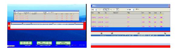
(d) (d) system remote signal status alarm system remote signal status alarm
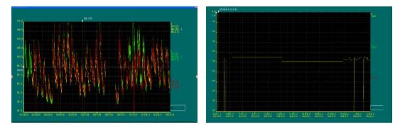
The system provides an analysis interface for the real-time curve and the historical trend curve, and analyzes the current load operation status of the circuit by calling the relevant loop real-time curve interface. For example, by calling a real-time curve of a distribution loop, the signal fluctuation caused by the electrical equipment of the loop can be analyzed. The historical trend of the system is that the system can view the historical trend of all stored data, which is convenient for engineers to analyze the quality of the monitored distribution network. (f) (f) Statistics of statements and statements
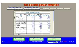
The active energy data collected by the system is automatically generated according to the name of the loop, and has a report printing function. It can query and print the electricity consumption in a certain period of time of a certain loop, and these reports can also be Excel. Format guide