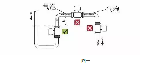
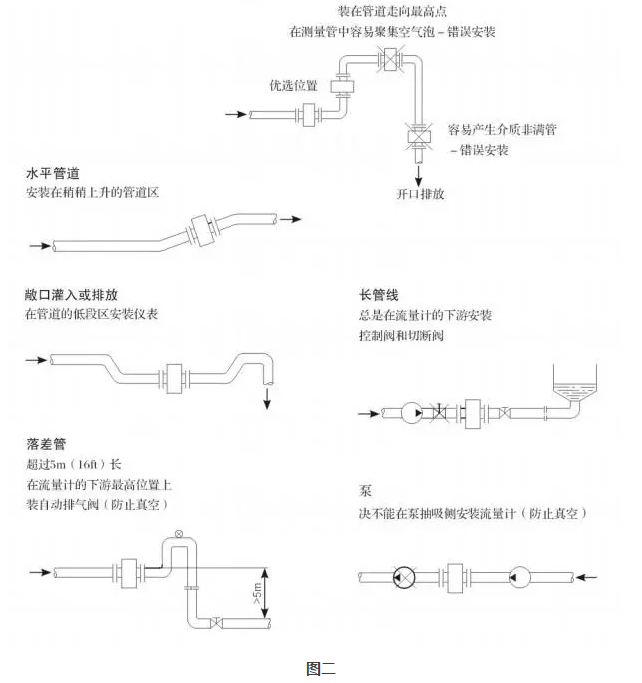
Electromagnetic flowmeters, we should not unfamiliar, but it looks very simple things, a head in a circle, in fact, there are a lot of mysteries where, every so often the problem off! Today we combine the on-site examples to analyze how to deal with problems encountered. First, the test liquid contains bubbles. This is a common phenomenon, which is caused by the inhalation of internal liquid and the dissolution of internal liquid. However, electromagnetic flowmeters cannot distinguish between liquid and air bubbles. Solution: 1. As shown in the above figure, it is not easy to install on the highest point of the pipe and replace the installation position. 2. If the installation location is not easy to replace, install the air collector upstream of the flow meter and vent regularly. Second, the liquid to be tested is not full. It can be said that the non-full pipe is an extreme case containing bubbles, which is not only the liquid in the pipe is full, but also contains a lot of bubbles on the top. If the liquid has not passed the electrode, the measurement result will be greatly reduced. This is an engineering mistake. Solution: Figure 2 mainly shows the installation of the electromagnetic flowmeter, and remember that it is correct. Third, the conductive layer short-circuit effect. As the conductive material is gradually deposited, a short circuit occurs in the flow signal. This type of fault does not usually appear during the commissioning period, but only after a period of time has elapsed. Solution: The flowmeter was disassembled and the insulating layer was cleaned. Most of the yellow rust occurred. This was due to the large amount of iron oxide deposited in the electrolyte. If you start to run normally and your traffic shows less and less over time, you should analyze the possibility of such failure. Fourth, encountered crystalline liquid. When selecting a type, you often encounter materials that are easily crystallized. Although most of the material can be normally measured at normal temperature, and the catheter has a heat insulating effect. However, the sensor measuring tube inside the flowmeter does not contain this function, so that when the regular fluid flows through the measuring tube, the inner wall is coated with a solid layer due to the temperature drop. Solution: 1. Try to choose a small flow meter. 2. Disassembly is more complicated and it is not recommended to choose such a flowmeter. Fifth, the liquid conductivity exceeds the allowable range. Since the output impedance of the electrode is determined by the conductivity of the liquid to be measured and the size of the electrode, when the conductivity is lower than the lower limit value, the instrument cannot work normally, and the display value shows shaking. Solution: According to the above problem, the factory is working properly after replacing the helium electrode electromagnetic flowmeter. 1. Select other low-conductivity electromagnetic flowmeters that meet the requirements, such as capacitive electromagnetic flowmeters 2. Use other principle flowmeters, such as orifices, etc. Six, space electromagnetic interference. In general, if the cable between the sensor and the converter is long and there is strong electromagnetic interference around the cable, the cable may introduce interference signals, causing common mode interference, resulting in display distortion, non-linearity or large shaking. Solution: 1. Try to stay away from strong magnetic fields (such as large motors, large transformers, and power cables). 2. Try to shorten the cable length and use shielding measures. VII. Asymmetric flow of the fluid to be measured. Under normal circumstances, it is required that the flow velocity in the pipeline is axisymmetric and the magnetic field is uniform. In practice, non-axisymmetric flow velocity distributions often occur. When vortex flow occurs, the output will be affected and errors will occur. Solution 1. There are enough straight sections in the upstream to ensure that the flow rate is concentric. 2. The inner diameter of the flowmeter should be the same as the inner diameter of the pipe in a certain range above and downstream, otherwise the flow velocity distribution will not be uniform. 3. If the upstream straight section is insufficient, a flow regulator can be installed so that only partial compensation can be made. Eight, the mounting point vibration problem. Electromagnetic flowmeters have strict requirements on the vibration of the installation point and must be installed in a place with low vibration, otherwise errors will occur. Auto Parts Used For Jinbei H2 Hiace Rear Bumper,Rear Pillar Assy For Hiace,Jinbei H2 Hiace Middle Door,Jinbei H2 Hiace Front Door Baoying Shuguang Auto parts Factory , https://www.shuguangautoparts.com